Week 1
In this module we are diving into the 3D aspects of Nuke, including the 3D viewport and 3D Nodes.
When setting up a camera in Nuke there are multiple things you need to make sure are correct, in order to match your virtual camera to your real one. These are your Focal Length, Resolution and Sensor.
First 3d nuke scene
Objects are placed in Nuke using nodes, here we use a “Card” node to place a plane, which we then texture using a “ColourBars” node. We then merge this node with our camera using the “Scene” node. Then we use the “ScanlineRender” node to render the scene as a 2D image, that can then be manipulated by our normal set of 2D nodes in Nuke.
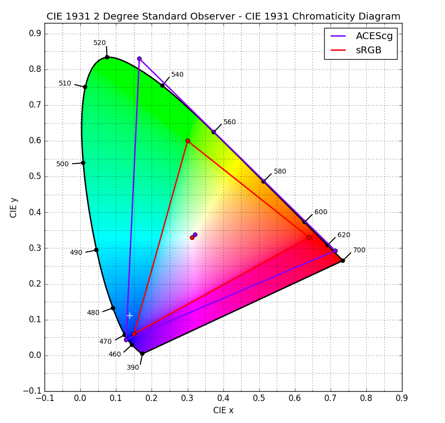
Colour Space
sRGB is the standard for most images. It is used in the JPEG image format.
We will be using ACEScg as it has a much deeper colour space.

Week 2
Undistorting and redistorting using STMaps
The first thing we need to do with any footage we are given is correct for the distortion of the camera lens. This means that when we add our 3D elements they will match the perspective of the shot. The camera distortion can then be added back in later.
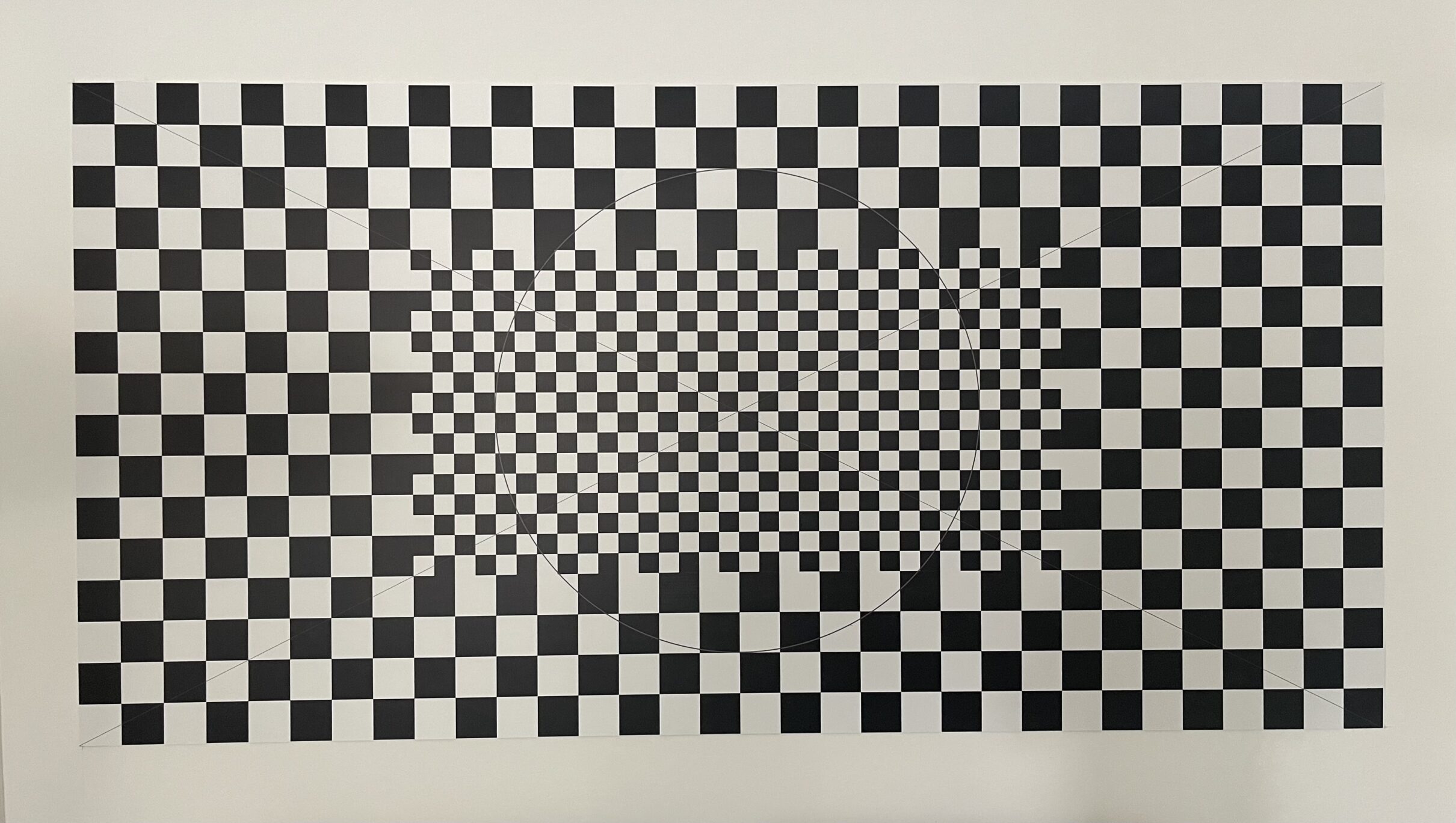
Information about the distortion of the lens should be provided to you by the client, this data can be gathered on set by shooting a checkerboard pattern, called a “Lens Distortion Grid.

A Lens Distortion Grid
Using camera tracker node
Week 3 – 3D Equaliser
In Week 3 we were introduced to 3D Equaliser, this is similar to the the 3D tracking in Nuke, however this dedicated software is more accurate and standard in the industry.
Week 8 – Lens Distortion
Extremely distorted source footage

When we try and track it in 3DE the track is very unstable, this is because we haven’t taken the lens distortion into account.
- We can remedy this by importing our lens distortion grid into 3DE and switching to “Distortion Grid” mode
- After lining up the grid we can calculate the distortion, and undistort the image
Assignment 1
Assignment 2
For Assignment 2 I decided to make a 1990s inspired F1 scene. We had a whole filming day to shoot our plates to composite our renders into. It was very useful to go through the whole process of a filming day, from noting down camera settings, to ingesting footage.
My chosen plate
Unfortunately we did not have a gimbal, so the footage ended up incredibly shaky, making it more difficult to track.
Tracking in 3De
The first step in the process was to track my chosen plate in 3D Equaliser.
The track required around 55~ points in total, the biggest difficulty I faced was the motion blur from the shaky camera causing 3DE to lose track of points.
I then corrected the distortion using footage of the grids we filmed that day, and also added in distance constraints using measurements I made of the real life scene. This all resulted in a fairly reasonable average tracking error of 0.7.
I then exported this track to Maya in order to create a render of my F1 Car.
First Test Render
Above is my first test render, bringing in the car render from Maya and laying it over the top of the plate footage, with some minor colour corrections.
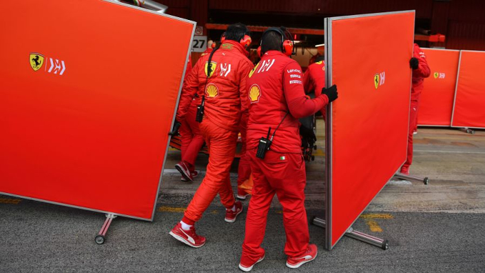
After this I also modelled a privacy screen in Maya to cover up the car in the background that was not in keeping with the 90s aesthetic.

A privacy screen, often used in F1
ASSIGNMENT 2 SUBMISSION – FINAL RENDER & NODE GRAPH
Further refinement – FINAL SUBMISSION ABOVE ^
After finishing, I played about with adding some VHS effects in Premier Pro to give the video a more 90s feel. I didn’t end up using this as the submission as we were not being marked for premier pro work, and it made evaluating the compositing more difficult.


